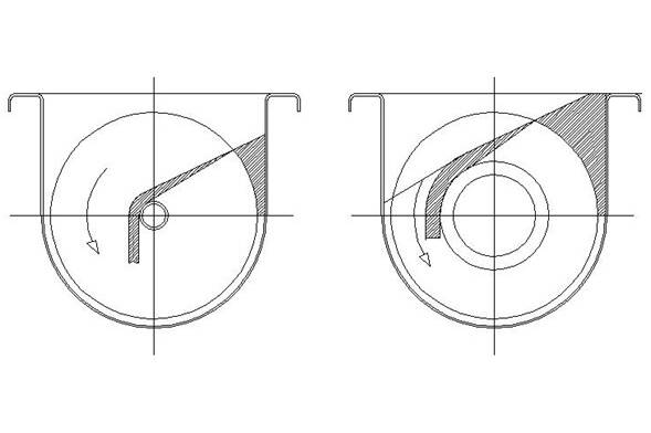
Whenever a bulk material is stored the contents are required to flow reliably and under control during both the filling and emptying processes. Few problems become apparent during filling, although some may be caused that show later. The regime of flow generated during the discharge process depends on the storage vessel construction and properties of the bulk material being handling, but essentially follows a mass or funnel flow form, depending whether the total stored contents move during discharge.
The two major benefits of Mass Flow are the securement of reliable flow without arching or ‘ratholing’ and the elimination of indeterminate residence time due to static regions of storage during discharge. Other benefits are secured are that the risk of ’flushing’ is reduced and that segregation that may have occurred during filling is redressed. It is essential for mass flow that extractions takes place over the entire area of the hopper outlet. However, to secure optimum performance, the drawdown from the outlet should also be as even as practical for the following reasons:
- To secure a uniform residence time of the hopper contents.
- To obtain a consistent density of the material on discharge.
- To homogenise or mix the hopper contents.
- To redress segregation occurred during filling.
- To minimise the risk of ‘flushing’.
- To minimise feeder drive power requirements.
Preferential extraction will take place from conical and pyramid shaped hoppers, especially those whose outlets are fitted with rotary vales or slide valves that are partially open. The situation is even more sensitive with plane flow hoppers that have slot outlets. Slot outlets are commonly employed on bulk storage hoppers. They are used to secure the benefits of plane flow and extra storage capacity due to their extended length and shallower hopper walls than are needed for radial flow regimes. The slot length should be at least three times and long as their width to secure the optimum benefits of plane flow and facilitate reliable flow through a width of the outlet slot that is about half the dimension required for a circular or square opening.
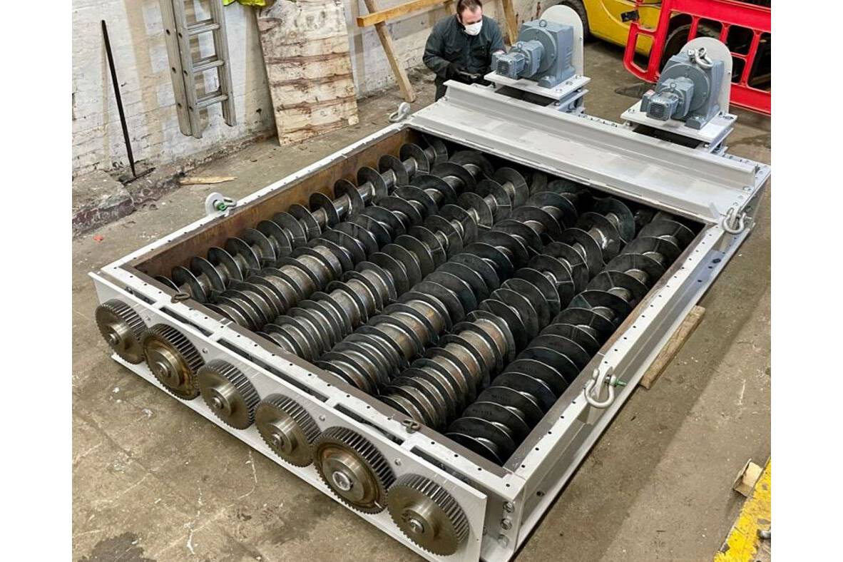
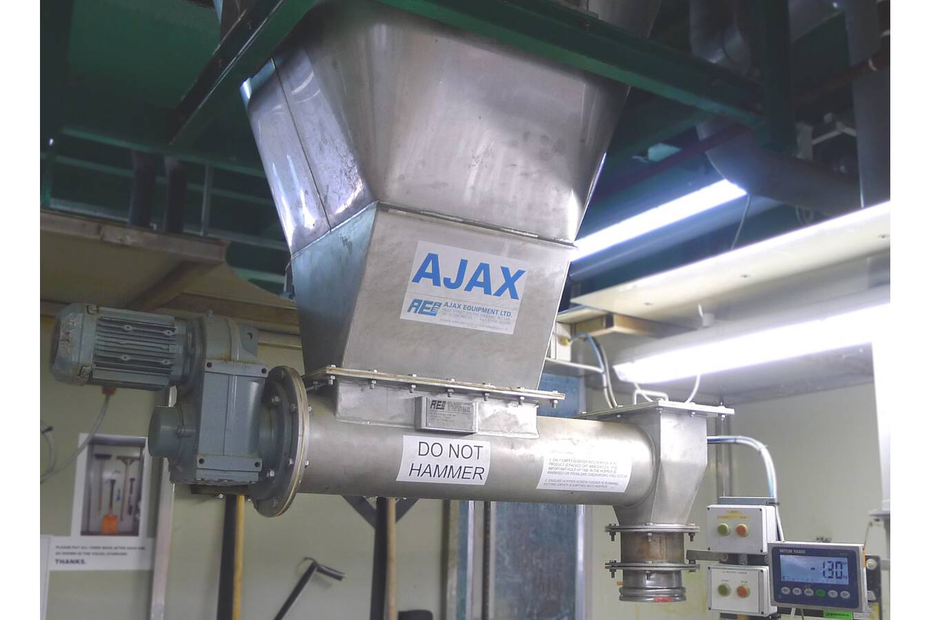
Screw feeders are commonly used to extract product from hoppers and varied techniques are employed to secure progressive extraction along the hopper outlet. However, uniform extraction is very rarely obtained by screw feeders for two reasons:
- linear increments in extraction capacity are required, but the initial extraction engages the full extraction area whereas subsequent extraction takes the only differential increase in extraction capacity.
- Pitch increases, commonly used to provide increased extraction, reduces the axial transport capacity, so does not proportional increase the extraction rate but does have to service a proportional increase in hopper outlet length. Consequently, this results in a decreased rate of extraction per unit length.
Ajax Equipment has developed a reg. design to mitigate the ‘initial draw’ feature and a combination of auger and casing construction to generate an extraction profile as even as economically practical. Another registered design by Ajax exploits the effect of surface friction on screw feeder flights to enable a reversing feeder to extract material progressively along a hopper outlet slot whilst feeding in either the forward and reverse direction independently to separate receiving points. The feeder can also deliver in both directions at the same time, in all cases at the chosen rate of discharge. This compact system carries all six of the operating benefits listed above and also saves considerable headroom over the conventional method of fitting a two-way valve and twin inclined chutes to deliver to two outlets.


")